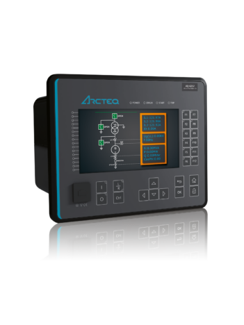
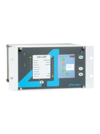
Generator and Motor Commander
Home Protection relays Generator protection & control Generator and Motor Commander
Description
Synchronous machine control and protection in one package!
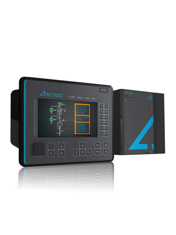
The Generator and Motor Commander is a new innovation that combines synchronous machine protection and control into a single device. Compared to traditional systems with several separate devices and multiple software, the Commander takes less space and saves considerable hours of engineering time. Additionally, its operation is smooth as there is only one interface to the system.
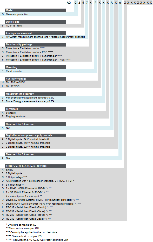
The Generator Commander has four software options for its AQ-G257x unit: the “C” variant (AQ-G257C) includes all the standard protection functions as well as excitation control; the “D” variant (AQ-G257D) also has the power system stabilizer (PSS); the “E” variant (AQ-G257E) has the standard protection functions, excitation control, and the synchronizer function; and the the “F” variant (AQ-G257F) has all the above-mentioned features from standard protection functions to excitation control, power system stabilizer (PSS), and synchronizer. For more details on the software options, please see the order code below.
Highlights:
Over 86% space savings compared to traditional solutions
Less spare parts needed
One easy-to-use software saves engineering time
The software wizard adapts the data from the generator specifications and calculates the majority of the parameters directly
Measurement accuracy of up to 0.2 %, robust technology, and the newest protection functions guarantee the best solution available on the market
Learn more about the Commander:
VIDEO
“Tame the Beasts with Generator and Motor Commander” by Arcteq Relays (https://youtu.be/1wAhC5D25Rc )
Technical data
AQ-G257C – Standard generator protection functionality + Excitation control
AQ-G257D – Standard generator protection functionality + Excitation control + PSS
AQ-G257E – Standard generator protection functionality + Excitation control + Synchronizer
AQ-G257F – Standard generator protection functionality + Excitation control + Synchronizer + PSS
AQ-M257C – Standard motor protection functionality + Excitation control
Non-directional overcurrent (I>; 50/51) - 4 stages (INST, DT or IDMT)
Non-directional earth fault (I0>; 50N/51N) - 4 stages (INST, DT or IDMT)
Directional overcurrent (Idir>; 67) - 4 stages (INST, DT or IDMT)
Directional earth fault (I0dir>; 67N/32N) - 4 stages (INST, DT or IDMT)
Negative sequence overcurrent/ Phase current reversal/ Current unbalance (I2>; 46/46R/46L) - 4 stages (INST, DT or IDMT)
Harmonic overcurrent (Ih>; 50H/51H/68H) - 4 stages (INST, DT or IDMT)
Circuit breaker failure protection (CBFP; 50BF/52BF)
High-impedance or low-impedance restricted earth fault/ Cable end differential (I0d>; 87N)
Overvoltage (U>; 59) - 4 stages (INST, DT or IDMT)
Undervoltage (U<; 27) - 4 stages (INST, DT or IDMT)
Neutral overvoltage (U0>; 59N) - 4 stages (INST, DT or IDMT)
Low-voltage ride-through (LVRT; 27T)
Sequence voltage (U1/U2>/<; 47/27P/59PN) - 4 stages (INST, DT or IDMT)
Overfrequency and underfrequency (f>/<; 81O/81U) - 8 stages (INST or DT)
Rate-of-change of frequency (df/dt>/<; 81R) - 8 stages (INST or DT)
Power protection (P, Q, S>/<; 32) - 4 stages (DT)
Generator/transformer differential (Idx>; 87T/87G/87M/87N)
100 % stator earth fault (U03rd>; 64S)
Underexcitation (Q<; 40)
Underimpedance (Z<; 21U)
Underreactance (X<; 21/40)
Voltage-restrained overcurrent (Iv>; 51V)
Inadvertent energizing (I>U<I.A.E.; 50/27)
Volts-per-hertz overexcitation (V/Hz>; 24)
Power factor protection (PF<; 55)
Pole slip/Out-of-step protection (78)
Machine thermal overload (TM>; 49M)
Voltage memory
Resistance temperature detectors (RTD)
Programmable stage (PGx>/<; 99)
Arc protection (IArc>/I0Arc>; 50Arc/50NArc) (optional)
Non-directional overcurrent (I>; 50/51) - 4 stages (INST, DT or IDMT)
Non-directional earth fault (I0>; 50N/51N) - 4 stages (INST, DT or IDMT)
Directional overcurrent (Idir>; 67) - 4 stages (INST, DT or IDMT)
Directional earth fault (I0dir>; 67N/32N) - 4 stages (INST, DT or IDMT)
Negative sequence overcurrent/ Phase current reversal/ Current unbalance (I2>; 46/46R/46L) - 4 stages (INST, DT or IDMT)
Harmonic overcurrent (Ih>; 50H/51H/68H) - 4 stages (INST, DT or IDMT)
Circuit breaker failure protection (CBFP; 50BF/52BF)
High-impedance or low-impedance restricted earth fault/ Cable end differential (I0d>; 87N)
Overvoltage (U>; 59) - 4 stages (INST, DT or IDMT)
Undervoltage (U<; 27) - 4 stages (INST, DT or IDMT)
Neutral overvoltage (U0>; 59N) - 4 stages (INST, DT or IDMT)
Sequence voltage (U1/U2>/<; 47/27P/59PN) - 4 stages (INST, DT or IDMT)
Overfrequency and underfrequency (f>/<; 81O/81U) - 8 stages (INST or DT)
Rate-of-change of frequency (df/dt>/<; 81R) - 8 stages (INST or DT)
Power protection (P, Q, S>/<; 32) - 4 stages (DT)
Generator/transformer differential (Idx>; 87T/87G/87M/87N)
Underexcitation (Q<; 40)
Underimpedance (Z<; 21U)
Underreactance (X<; 21/40)
Voltage-restrained overcurrent (Iv>; 51V)
Inadvertent energizing (I>U<I.A.E.; 50/27)
Volts-per-hertz overexcitation (V/Hz>; 24)
Power factor protection (PF<; 55)
Pole slip/Out-of-step protection (78)
Motor status monitoring
Machine thermal overload (TM>; 49M)
Motor start/ Locked rotor monitoring (Ist>; 48/14)
Frequent start (N>; 66)
Non-directional undercurrent (I<; 37)
Mechanical jam (Im>; 51M)
Voltage memory
Resistance temperature detectors (RTD)
Programmable stage (PGx>/<; 99)
Arc protection (IArc>/I0Arc>; 50Arc/50NArc) (optional)
Number of objects to control and monitor: 10
Number of indicators to monitor: 10
Number of setting groups: 8
Vector jump (Δφ; 78)
Synchrocheck (ΔV/Δa/Δf; 25)
Synchronizer (ΔV/Δa/Δf; 25) (optional)
Excitation with external IGBT bridge
Phase, sequence and residual currents (IL1, IL2, IL3, I01, I02)
Phase, sequence and residual voltages (UL1, UL2, UL3, UL12, UL23, UL31, U0)
Frequency (f)
Power (P, Q, S, pf) and Energy (E+, E-, Eq+, Eq-)
Power and energy measurement accuracy of 0.5 %
Power and energy measurement accuracy of up to 0.2 % (optional)
Current transformer supervision - 2 instances
Voltage transformer supervision (60)
Circuit breaker wear monitoring
Total harmonic distortion (current)
Total harmonic distortion (voltage)
Measurement recorder
Measurement value recorder
Event recorder (max. 15 000 permanent event records)
Disturbance recorder (max. 100 records á 5 seconds at 3.2 kHz sampling)
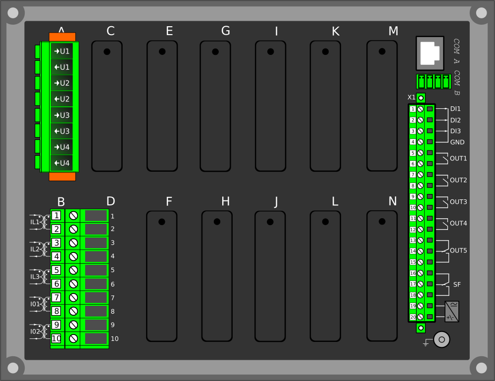
Current inputs: 10
Voltage inputs: 4
Digital inputs (fixed): 3
Digital outputs (fixed): 5
Number of empty slots: 9
Digital input module (8 x DI) (optional)
Digital output module (5 x DO) (optional)
High-speed high-current output module (3 x out) (optional)
Milliampere input module (4 x mA in, 1 x mA out) (optional)
Milliampere output module (4 x mA out, 1 x mA in) (optional)
RTD input module (8 RTD inputs) (optional)
Arc protection module (4 x channels, 2 x HSO, 1 x BI) (optional)
Communication media (see "Communication" below)
External I/O modules (see "Accessories" below)
Communication inputs
RJ-45 100 Mbps Ethernet (front panel, fixed)
RJ-45 100 Mbps Ethernet and RS-485 (rear panel, fixed)
Double RJ-45 Ethernet & IRIG-B communication module (optional)
Double ST Ethernet & IRIG-B communication module (optional)
Double SFP Ethernet & IRIG-B communication module (optional)
Double LC (HSR/PRP) Ethernet communication module (optional)
Double RJ-45 (HSR/PRP) Ethernet communication module (optional)
RS-232 & serial fiber communication module (optional)
Communication protocols
IEC 61850 (edition 1)
IEC 61850 (edition 2)
IEC 60870-5-101/104
IEC 60870-5-103
Modbus/RTU and Modbus/TCP
DNP3
SPA
AX007 External 6-channel 2-/3-wire RTD input module (pre-configured)
AX008 External 8-channel thermocouple and mA input module (pre-configured)
AX013 Raising frame (120 mm)
AX014 Raising frame (40 mm)
AX015 Wall mounting bracket
AX020 SFP module (2 km, MM)
AX021 SFP module (40 km, SM)
AX022 SFP module (120 km, SM)
Download
AQ 200 series flyer, v2.01 (English)
AQ 200 series flyer, v2.01 (Finnish)
AQ 200 series flyer, v2.01 (Swedish)
AQ 200 series product catalog (ANSI, v2.03, EN, September 2024)
AQ 200 series product catalog (IEC, v2.03, EN, September 2024)
AQtivate PRO flyer, v1.00 (English)
AQtivate PRO flyer, v1.00 (Finnish)
Generator and Motor Commander Brochure v1.02 (English)
Generator Commander product flyer, v1.00 (Finnish)