AQ-R215 Railway Protection Device
Home Protection relays Railway protection AQ-R215 Railway Protection Device
Description
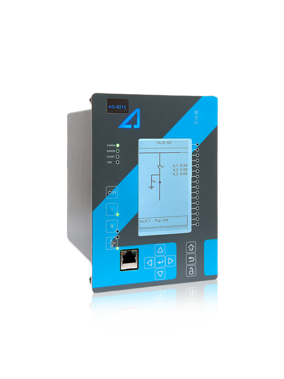
AQ-R215 is a three-phase feeder protection device that can be run either in Standard feeder mode or in Railway mode. In the Railway mode the device provides a single-phase overcurrent, earth fault, and voltage protection. Each protection stage can be independently set to the frequency of 16 2/3 Hz or of 50/60 Hz. When in the Standard mode the functionality of AQ-R215 is identical to that of AQ-F215 Feeder Protection Device. In this mode the relay can also be dynamically set to run on a frequency between 6 and 75 Hz.
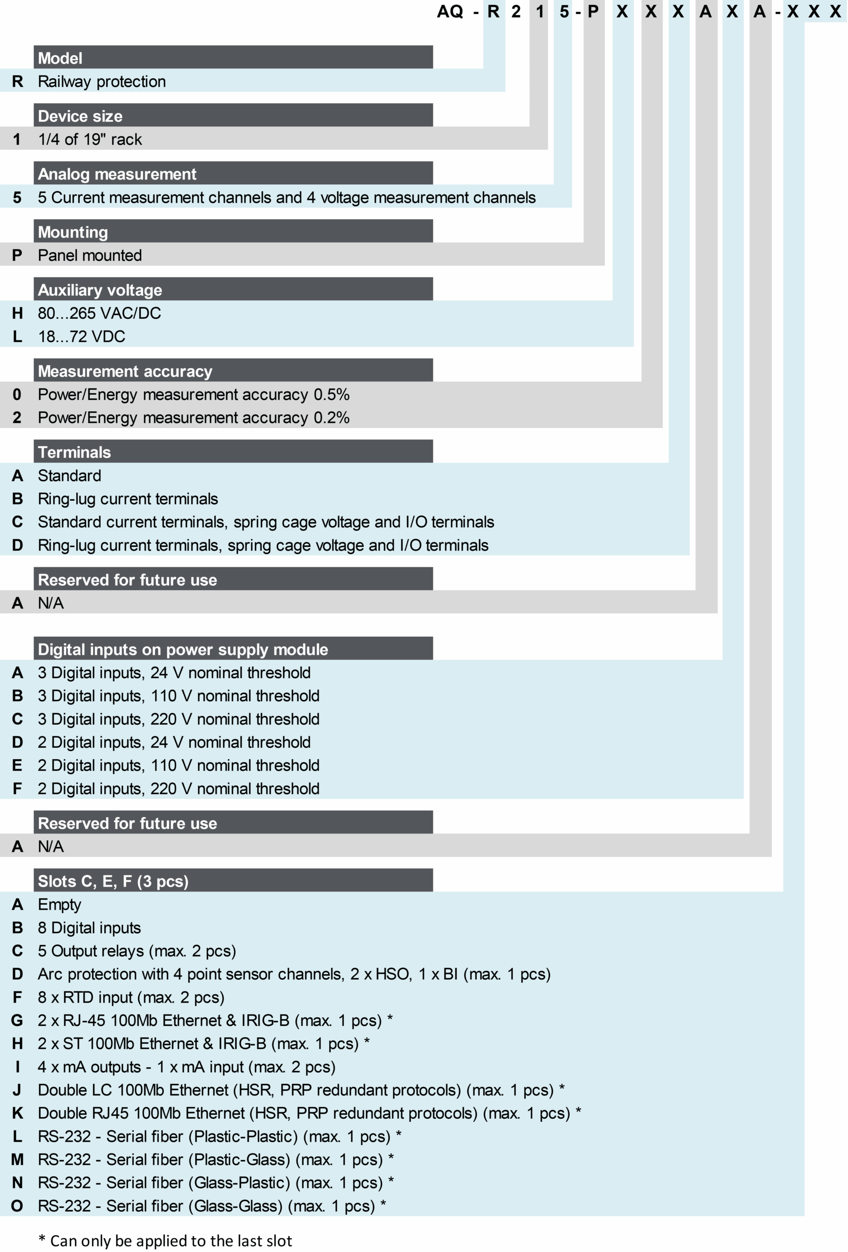
You can add up to three (3) I/O or communication cards into the device for more demanding control, alarm and indication needs. AQ-R215 communicates using various protocols, including communication according to the IEC 61850 standard.
Highlights:
Single-phase protection for any frequency range between 6 and 75 Hz.
Double busbar control.
Directional overcurrent and voltage protection.
Low-impedance restricted earth fault protection.
Harmonics protection and control.
5-shot scheme-controlled auto-recloser.
Technical data
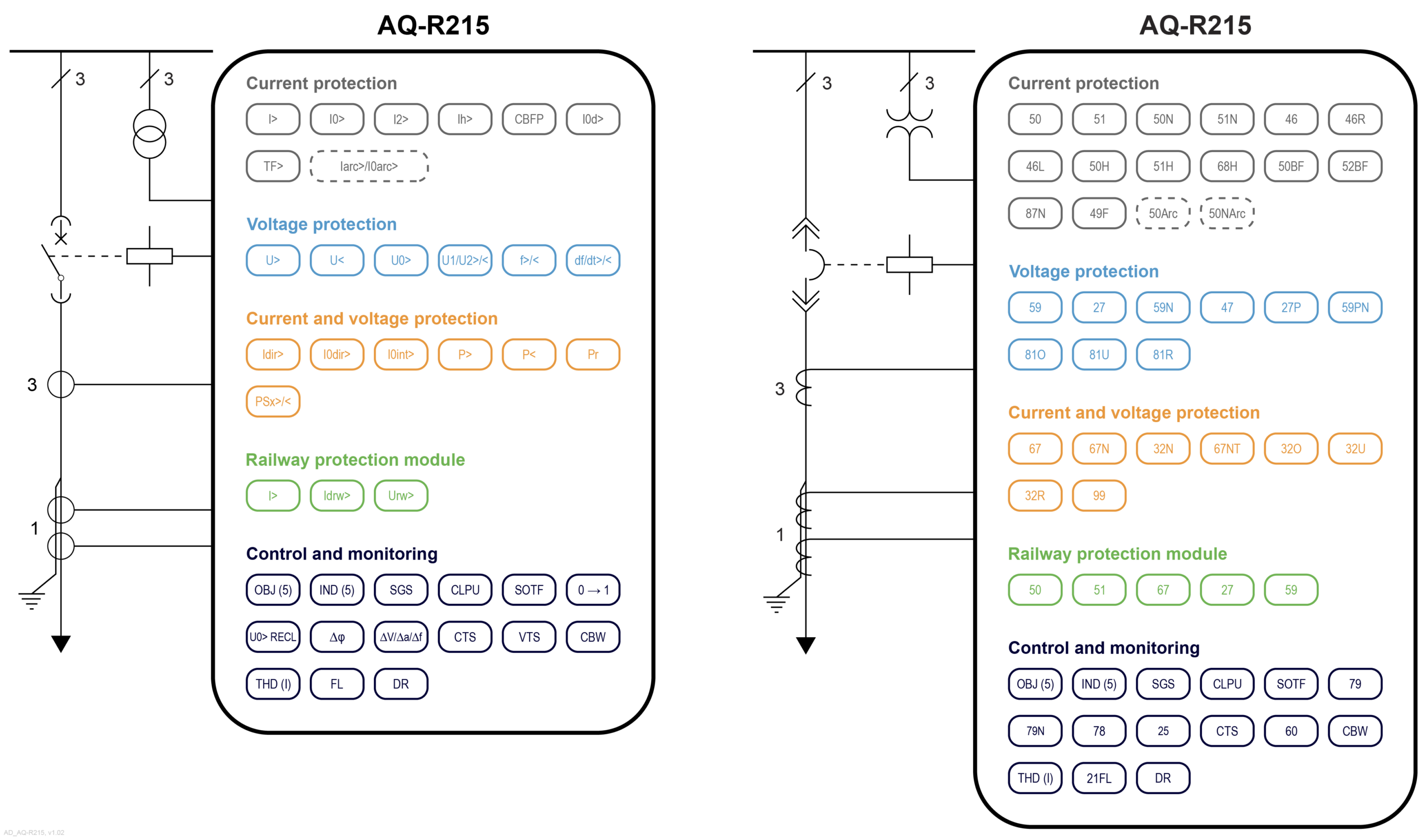
Railway non-directional overcurrent (I>; 50/51) - 4 stages
Railway directional overcurrent (Idrw>) - 8 stages
Railway voltage (Urw>/<; 27/59) - 4 stages
Non-directional overcurrent (I>; 50/51) - 4 stages
Non-directional earth fault (I0>; 50N/51N) - 4 stages
Directional overcurrent (Idir>; 67) - 4 stages
Directional earth fault (I0dir>; 67N/32N) - 4 stages
Intermittent earth fault (I0int>; 67NT)
Negative sequence overcurrent/ Phase current reversal/ Current unbalance (I2>; 46/46R/46L) - 4 stages
Harmonic overcurrent (Ih>; 50H/51H/68H) - 4 stages
Circuit breaker failure protection (CBFP; 50BF/52BF)
High-impedance or low-impedance restricted earth fault/ Cable end differential (I0d>; 87N)
Overvoltage (U>; 59) - 4 stages
Undervoltage (U<; 27) - 4 stages
Neutral overvoltage (U0>; 59N) - 4 stages
Sequence voltage (U1/U2>/<; 47/27P/59PN) - 4 stages
Overfrequency and underfrequency (f>/<; 81O/81U) - 8 stages
Rate-of-change of frequency (df/dt>/<; 81R) - 8 stages
Overpower (P>; 32O)
Underpower (P<; 32U)
Reverse power (Pr; 32R)
Line thermal overload (TF>; 49F)
Programmable stage (PSx>/<; 99)
Arc protection (IArc>/I0Arc>; 50Arc/50NArc) (optional)
Number of objects to control and monitor: 5
Number of indicators to monitor: 5
Number of setting groups: 8
Cold load pick-up (CLPU)
Switch-on-to-fault (SOTF)
Auto-recloser (0 → 1; 79)
Zero sequence recloser (U0> RECL; 79N)
Vector jump (Δφ; 78)
Synchrocheck (ΔV/Δa/Δf; 25)
Current transformer supervision
Voltage transformer supervision (VTS; 60)
Circuit breaker wear monitoring
Total harmonic distortion (current)
Fault locator (21FL)
Measurement recorder
Measurement value recorder
Event recorder (max. 15,000 permanent event records)
Disturbance recorder (max. 100 records á 5 seconds at 3.2 kHz sampling)
Phase, sequence and residual currents (IL1, IL2, IL3, I01, I02)
Phase, sequence and residual voltages (UL1, UL2, UL3, UL12, UL23, UL31, U0)
Frequency (f)
Power (P, Q, S, pf) and Energy (E+, E-, Eq+, Eq-)
Power and energy measurement accuracy of 0.5 %
Power and energy measurement accuracy of up to 0.2 % (optional)
Standard hardware
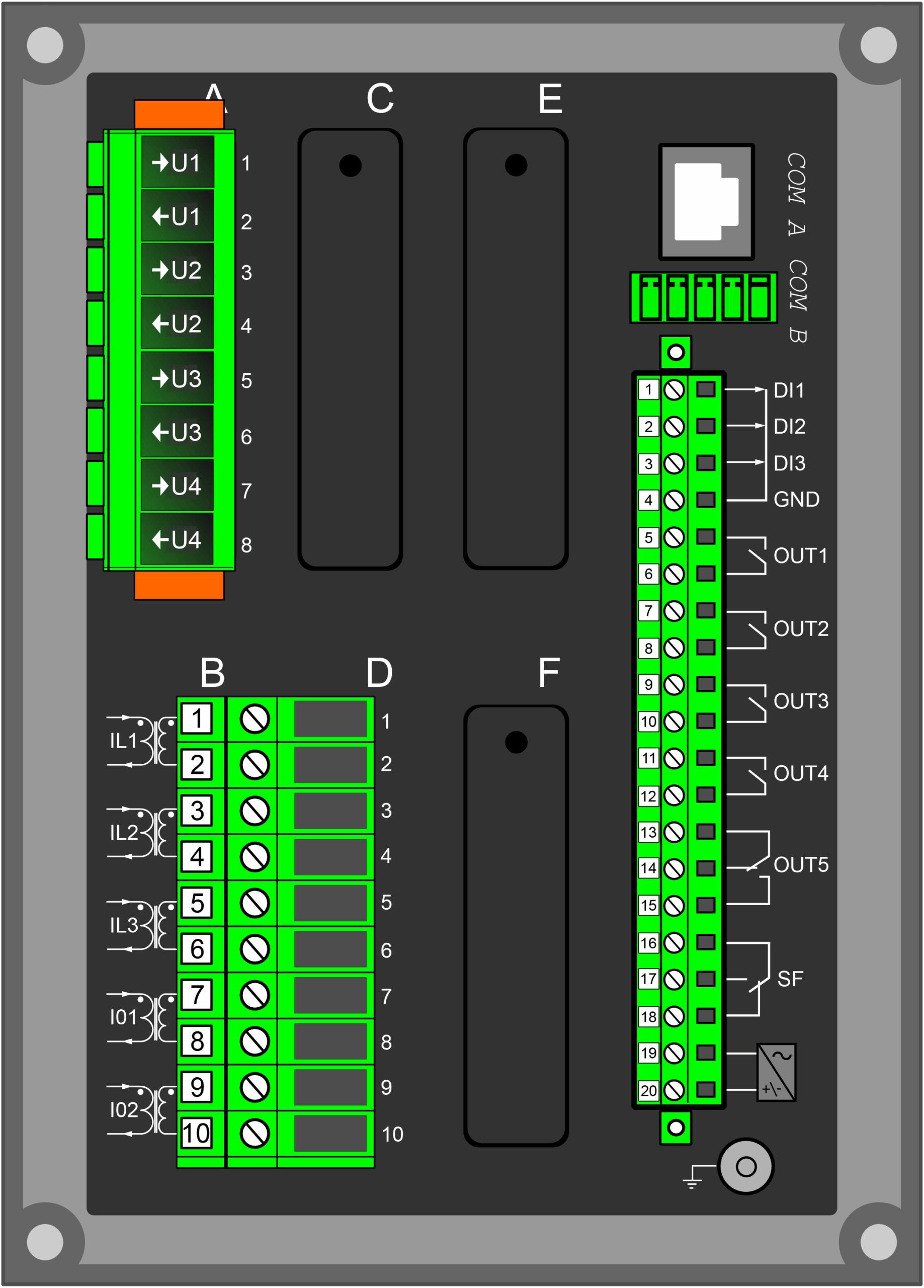
Current inputs: 5
Voltage inputs: 4
Digital inputs: 3
Digital outputs: 5
Number of empty slots: 3
Optional hardware modules
Digital input module (8 x DI)
Digital output module (5 x DO)
Milliampere output module (4 x mA out, 1 x mA in)
RTD input module (8 RTD inputs)
Arc protection module (4 x channels, 2 x HSO, 1 x BI)
Communication media (see "Communication" below)
External I/O modules (see "Accessories" below)
Standard communication ports
RJ-45 100 Mbps Ethernet (front panel)
RJ-45 100 Mbps Ethernet and RS-485 (rear panel)
Optional communication modules
Double RJ-45 Ethernet & IRIG-B communication module
Double ST Ethernet & IRIG-B communication module
Double LC (HSR/PRP) Ethernet communication module
Double RJ-45 (HSR/PRP) Ethernet communication module
RS-232 & serial fiber communication module
Communication protocols
IEC 61850 (edition 1)
IEC 60870-5-101/104
IEC 60870-5-103
Modbus/RTU and Modbus/TCP
DNP3
SPA
AX007 External 6-channel 2-/3-wire RTD input module (pre-configured)
AX008 External 8-channel thermocouple and mA input module (pre-configured)
AX009 Raising frame (87 mm)
AX010 Raising frame (40 mm)
AX011 Combiflex frame
AX012 Wall mounting bracket