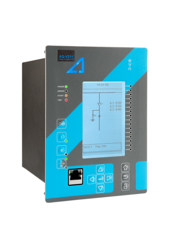
AQ-V251 Voltage Protection Device
Home Protection relays Voltage protection AQ-V251 Voltage Protection Device
Description
AQ-V251x offers a modular voltage protection solution for substations. The relay includes both voltage and frequency protections as well as powerful logic programming, and you can add up to thirteen (13) I/O or communication cards. All this makes AQ-V251x optimal for demanding load shedding and automatic transfer applications that require a large I/O capacity. AQ-V251x communicates using various protocols, including the IEC 61850 substation communication standard.
AQ-V251x comes in two variants: AQ-V251A has all the I/O capacity and protections, while AQ-V251B also includes the synchronizer control function.
Configure AQ-V251A in the Product Configurator
Configure AQ-V251B in the Product Configurator
Highlights:
A large I/O capacity.
Eight (8) frequency stages and eight (8) setting groups for load shedding.
Synchrocheck for up to three (3) circuit breakers.
Anti-islanding protection.
Technical data
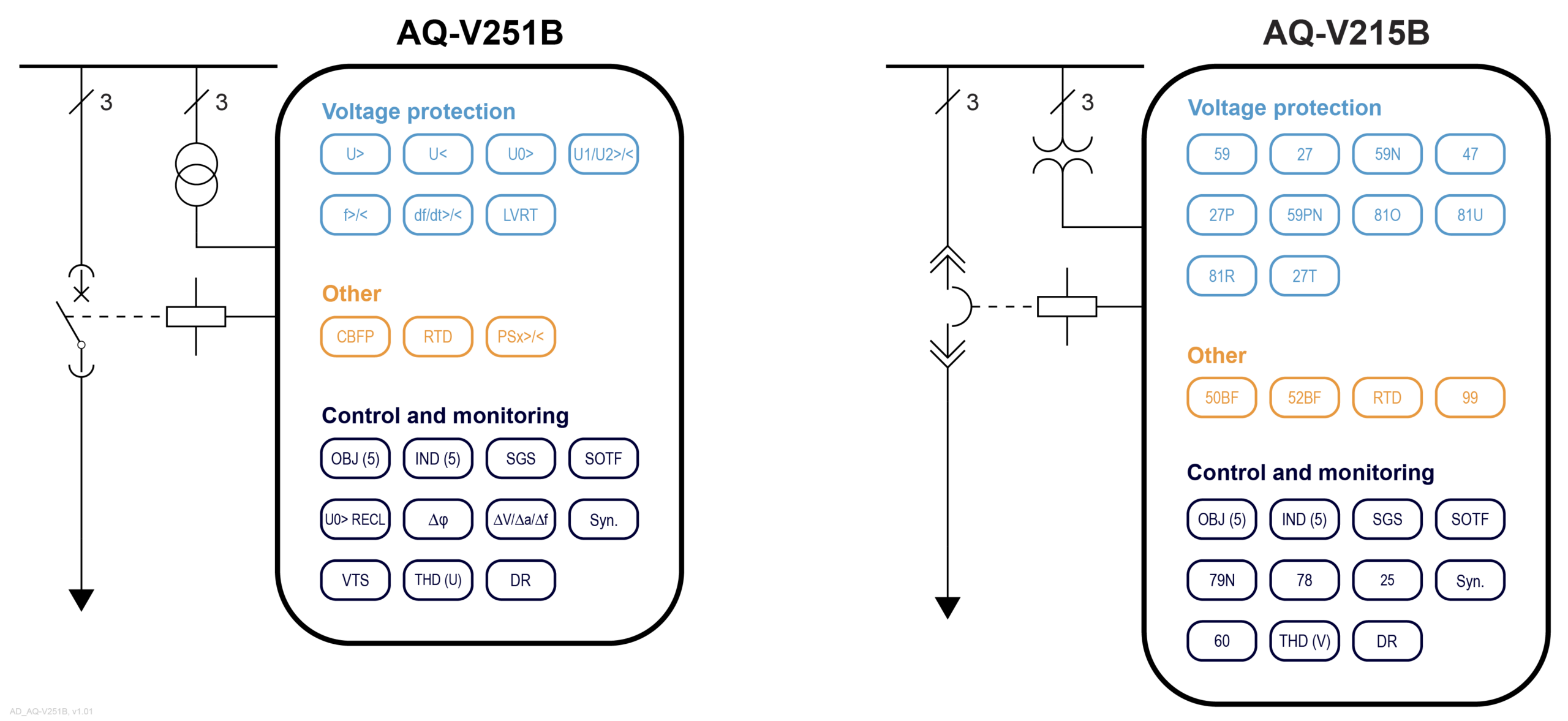
Overvoltage (U>; 59) - 4 stages
Undervoltage (U<; 27) - 4 stages
Neutral overvoltage (U0>; 59N) - 4 stages
Sequence voltage (U1/U2>/<; 47/27P/59PN) - 4 stages
Overfrequency and underfrequency (f>/<; 81O/81U) - 8 stages
Rate-of-change of frequency (df/dt>/<; 81R) - 8 stages
Low-voltage ride-through (LVRT; 27T)
Circuit breaker failure protection (CBFP; 50BF/52BF)
Resistance temperature detectors (RTD)
Programmable stage (PSx>/<; 99)
Number of objects to control and monitor: 10
Number of indicators to monitor: 10
Number of setting groups: 8
Switch-on-to-fault (SOTF)
Zero sequence recloser (U0> RECL; 79N)
Vector jump (Δφ; 78)
Synchrocheck (ΔV/Δa/Δf; 25)
Number of objects to control and monitor: 10
Number of indicators to monitor: 10
Number of setting groups: 8
Switch-on-to-fault (SOTF)
Zero sequence recloser (U0> RECL; 79N)
Vector jump (Δφ; 78)
Synchrocheck (ΔV/Δa/Δf; 25)
Synchronizer (ΔV/Δa/Δf; 25)
Voltage transformer supervision (VTS; 60)
Measurement recorder
Measurement value recorder
Event recorder (max. 15,000 permanent event records)
Disturbance recorder (max. 100 records á 5 seconds at 3.2 kHz sampling)
Phase, sequence and residual voltages (UL1, UL2, UL3, UL12, UL23, UL31, U0)
Frequency (f)
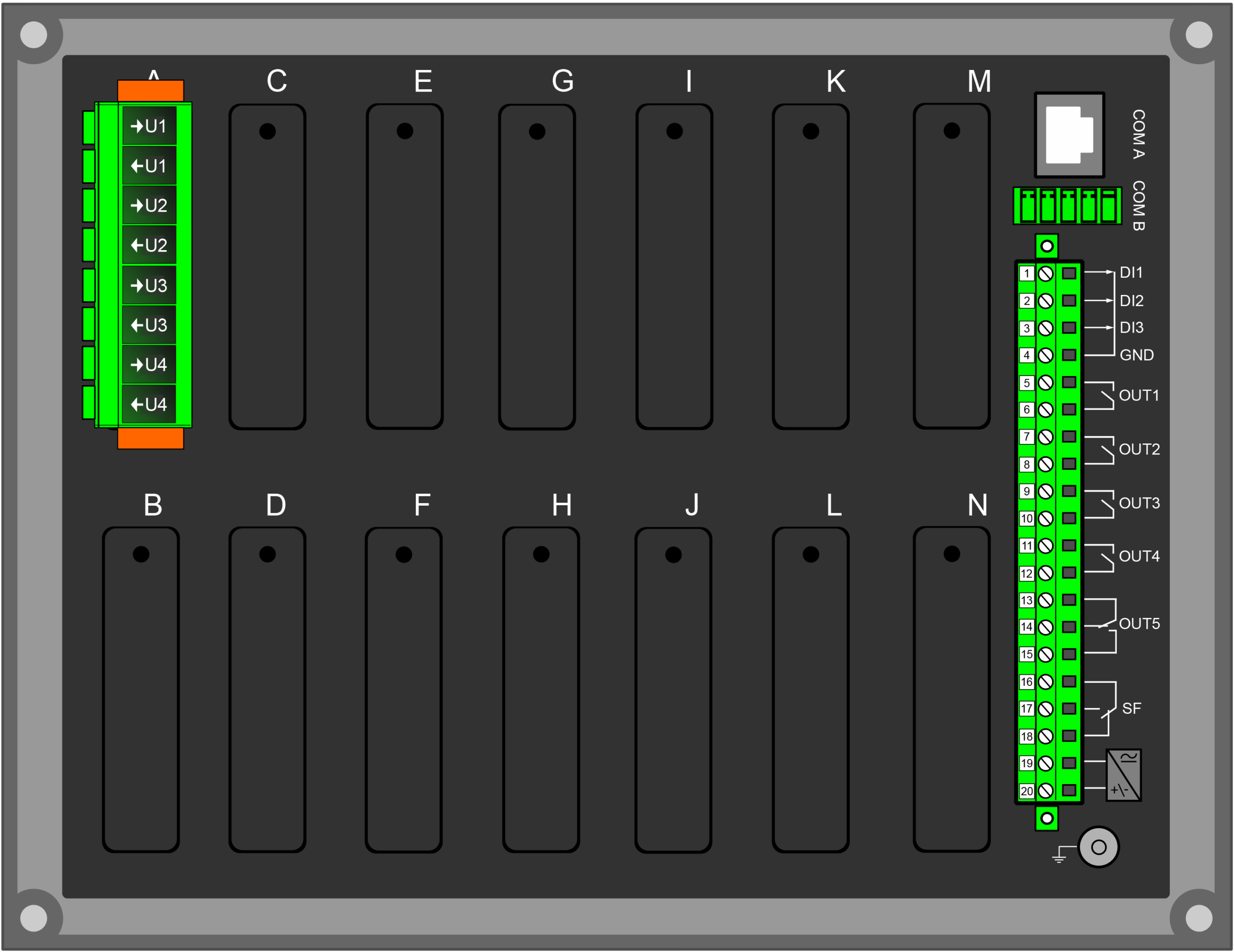
Standard hardware
Voltage inputs: 4
Digital inputs: 3
Digital outputs: 5
Number of empty slots: 13
Optional hardware modules
Digital input module (8 x DI)
Digital output module (5 x DO)
High-speed high-current output module (3 x out)
Milliampere input module (4 x mA in, 1 x mA out)
Milliampere output module (4 x mA out, 1 x mA in)
RTD input module (8 RTD inputs)
Arc protection module (4 x channels, 2 x HSO, 1 x BI)
Communication media (see "Communication" below)
External I/O modules (see "Accessories" below)
Standard communication ports
RJ-45 100 Mbps Ethernet (front panel)
RJ-45 100 Mbps Ethernet and RS-485 (rear panel)
Optional communication modules
Double RJ-45 Ethernet & IRIG-B communication module
Double ST Ethernet & IRIG-B communication module
Double SFP Ethernet & IRIG-B communication module
Double LC (HSR/PRP) Ethernet communication module
Double RJ-45 (HSR/PRP) Ethernet communication module
RS-232 & serial fiber communication module
Communication protocols
IEC 61850 (edition 1)
IEC 61850 (edition 2)
IEC 60870-5-101/104
IEC 60870-5-103
Modbus/RTU and Modbus/TCP
DNP3
SPA
AX007 External 6-channel 2-/3-wire RTD input module (pre-configured)
AX008 External 8-channel thermocouple and mA input module (pre-configured)
AX013 Raising frame (120 mm)
AX014 Raising frame (40 mm)
AX015 Wall mounting bracket
AX020 SFP module (2 km, MM)
AX021 SFP module (40 km, SM)
AX022 SFP module (120 km, SM)