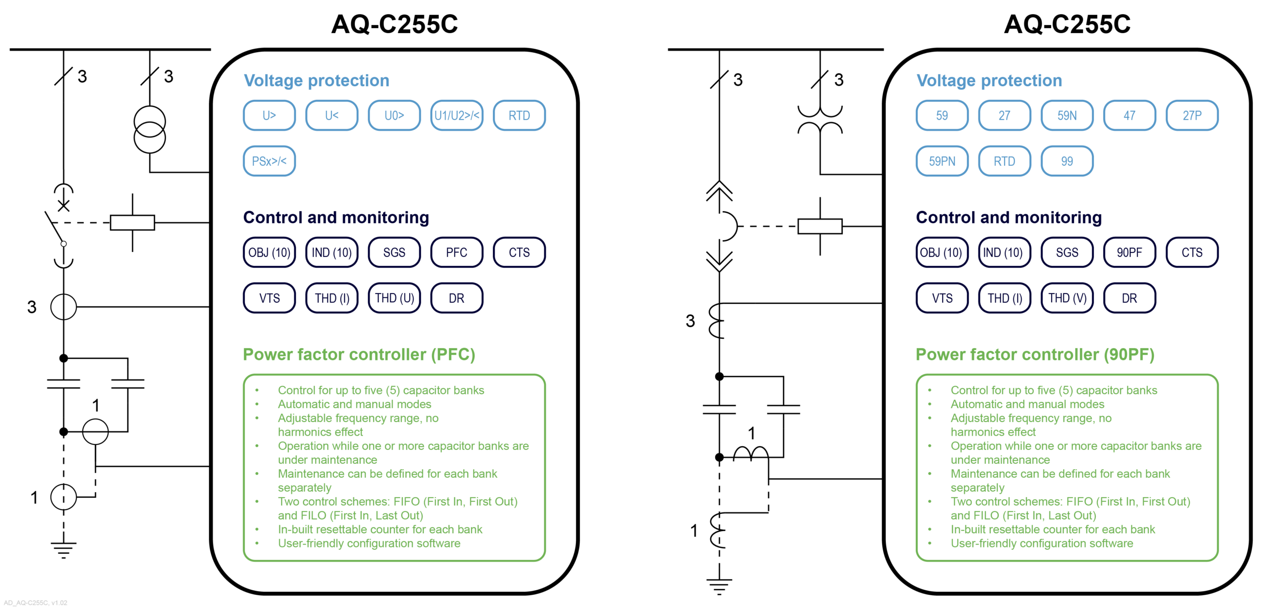
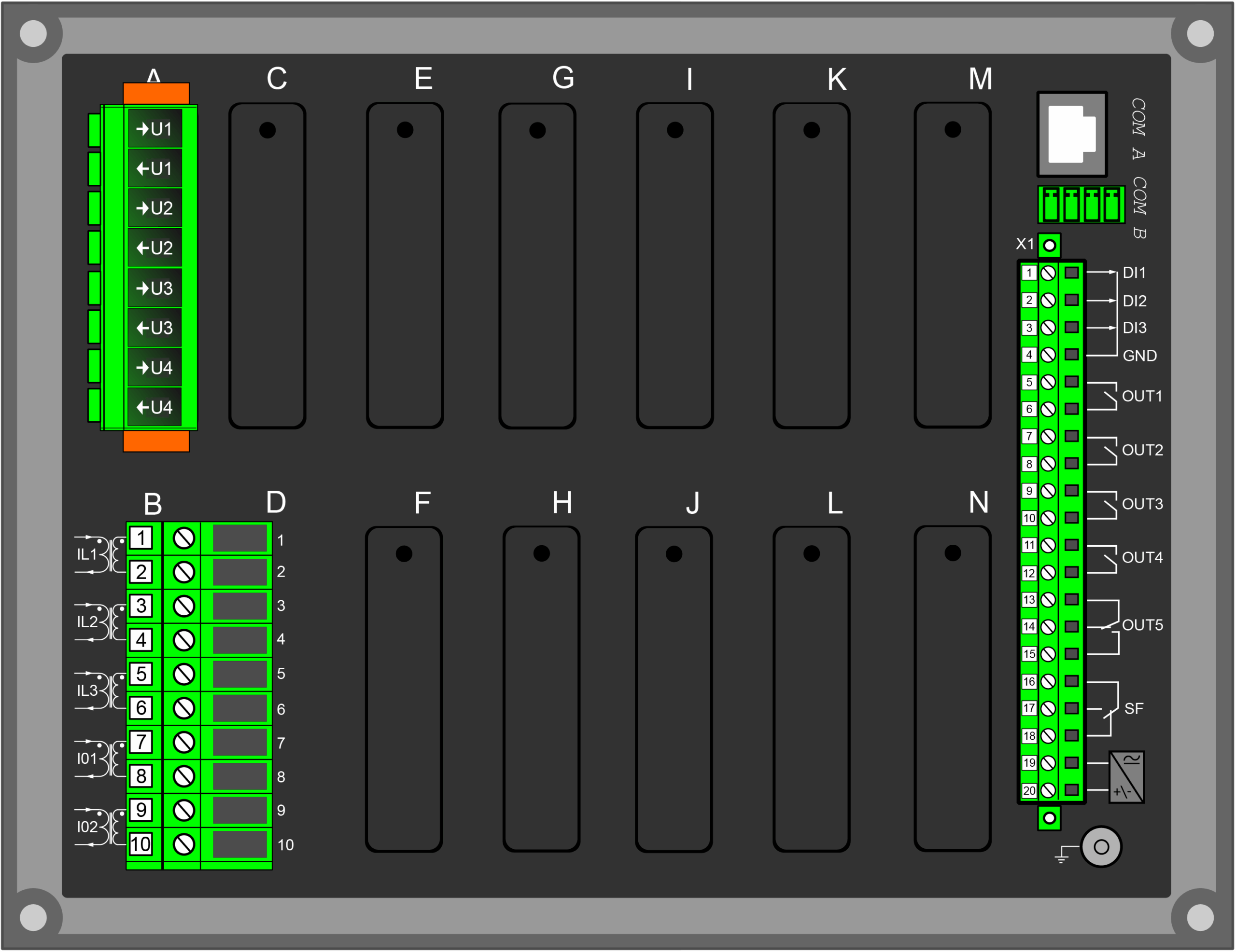
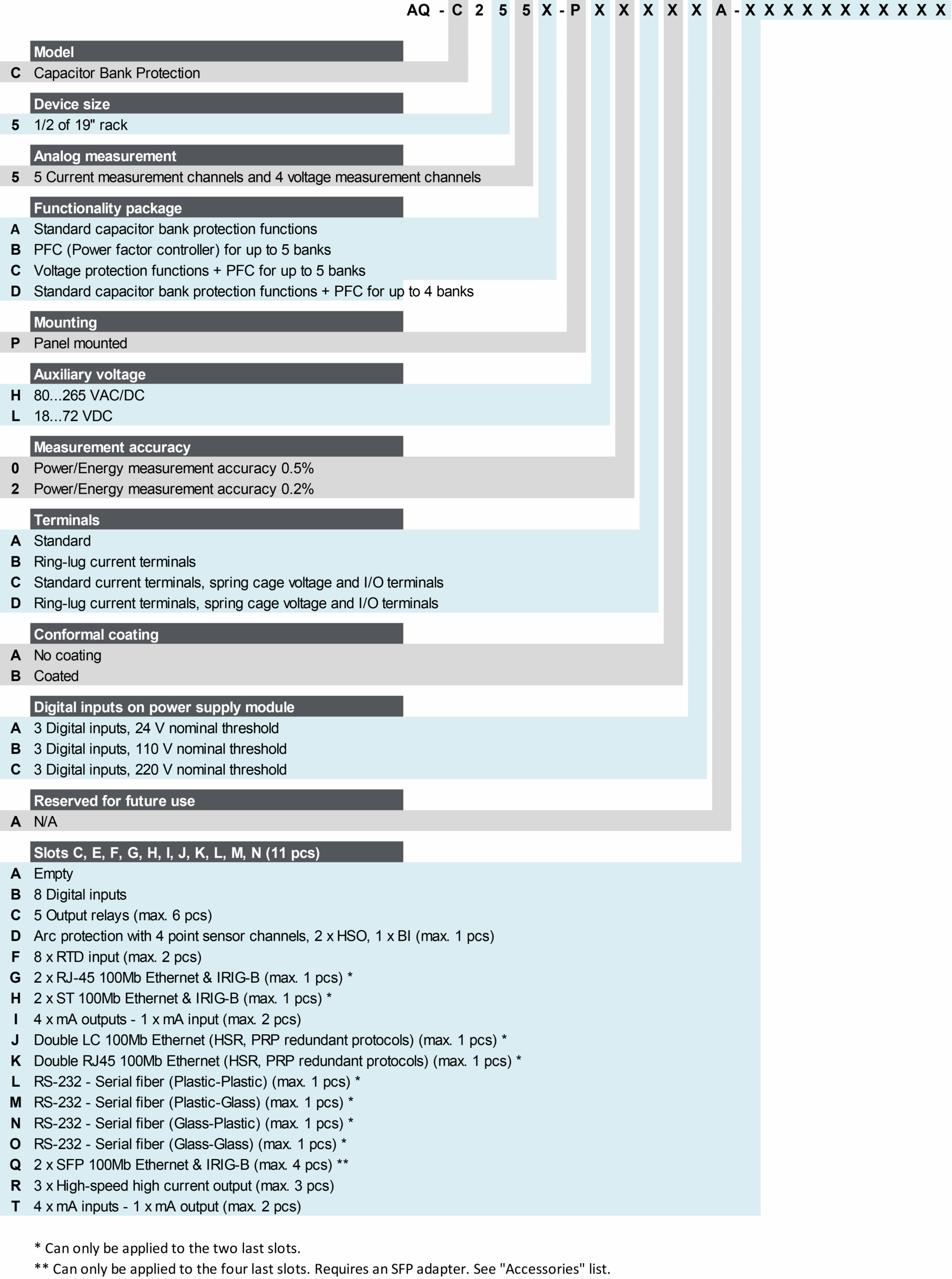
AQ-C255C Capacitor bank protection device
AQ-C255B-D
AQ-C255B-D

Description

The AQ-C255C capacitor bank protection device has been specifically designed for the protection of capacitor banks. It includes voltage protections in addition to the new power factor controller that functions as the control unit of an automatic capacitor bank system and can control up to five (5) capacitor banks. AQ-C255C offers a modular protection and control solution for applications that require a large I/O capacity. You can add up to eleven (11) I/O or communication modules into the device for extensive monitoring and control applications. The AQ-C255C capacitor bank protection device communicates using various protocols, including the IEC 61850 substation communication standard.

Highlights:

  • A large I/O capacity.
  • Voltage-based protections.
  • Power factor controller for up to five (5) capacitor banks.
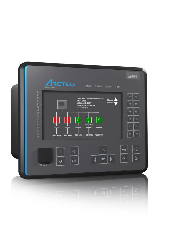
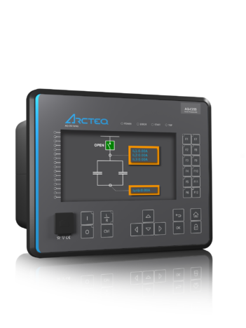
  • A controllable color mimic with active feedback.
  • Power and energy measurement accuracy of up to 0.2 %.

See all AQ-C255 variants

AQ-C255B-D

Technical data

  • Circuit breaker failure protection (CBFP; 50BF/52BF)
  • Overvoltage (U>; 59) - 4 stages (INST, DT or IDMT)
  • Undervoltage (U<; 27) - 4 stages (INST, DT or IDMT)
  • Neutral overvoltage (U0>; 59N) - 4 stages (INST, DT or IDMT)
  • Sequence voltage (U1/U2>/<; 47/27P/59PN) - 4 stages (INST, DT or IDMT)
  • Overfrequency and underfrequency (f>/<; 81O/81U) - 8 stages (INST or DT)
  • Rate-of-change of frequency (df/dt>/<; 81R) - 1 stage (DT)
  • Power protection (P, Q, S>/<; 32) - 4 stages (DT)
  • Resistance temperature detectors (RTD)
  • Voltage memory

  • Number of objects to control and monitor: 10
  • Number of indicators to monitor: 10
  • Number of setting groups: 8
  • Power factor controller (PFC) - up to 5 banks
  • Switch-on-to-fault

  • Phase, sequence and residual voltages (UL1, UL2, UL3, U12, U23, U31, U0)
  • Voltage transformer supervision (60)
  • Measurement recorder
  • Measurement value recorder
  • Event recorder (max. 15 000 permanent event records)
  • Disturbance recorder (max. 100 records á 5 seconds at 3.2 kHz sampling)

  • Voltage inputs: 4
  • Digital inputs (fixed): 3
  • Digital outputs (fixed): 5
  • Number of empty slots: 11
  • Digital inputs: +8/16/24/32/40/48/56/64/72/80/88 (optional)
  • Digital outputs: +5/10/15/20/25/30 (optional)
  • Milliampere I/O module (4 mA outputs + 1 mA input)
  • Communication media (see "Communication" below)
  • External I/O modules (see "Accessories" below)

  • Communication inputs
  • RJ-45 100 Mbps Ethernet (front panel, fixed)
  • RJ-45 100 Mbps Ethernet and RS-485 (rear panel, fixed)
  • 2 x RJ-45 100 Mbps Ethernet with an IRIG-B input (optional)
  • 2 x ST 100 Mbps Ethernet with an IRIG-B input (optional)
  • 2 x LC 100 Mbps Ethernet (PRP/HSR) (optional)
  • RS-232 serial fiber (PP/PG/GP/GG) (optional)
  • Communication protocols
  • IEC 61850 (edition 1)
  • IEC 61850 (edition 2)
  • IEC 60870-5-101/104
  • IEC 60870-5-103
  • Modbus/RTU and Modbus/TCP
  • DNP3
  • SPA

  • AX007 External 6-channel 2-/3-wire RTD input module (pre-configured)
  • AX008 External 8-channel thermocouple and mA input module (pre-configured)
  • AX013 Raising frame (120 mm)
  • AX014 Raising frame (40 mm)
  • AX015 Wall mounting bracket

Additional material

Application Drawing

An application image for AQ-C255C capacitor bank protection device with a power factor controller for up to five banks, as well as voltage protection, with one version drawn according to IEC standard symbols and the other according to IEEE/ANSI standard symbols.

Device Rear Image

Device rear image_AQ-255-AAAAAAAAA

Device and Cut-out Image

AQ-250 dimensions and cut-out

Order Code

C255x

Related products

Ask for an offer or more information

We provide a comprehensive range of services through our own skilled staff and a global network of partners.