AQ-F255E Line Differential and Distance Protection Device
AQ-F255_web
AQ-F255_web

Description

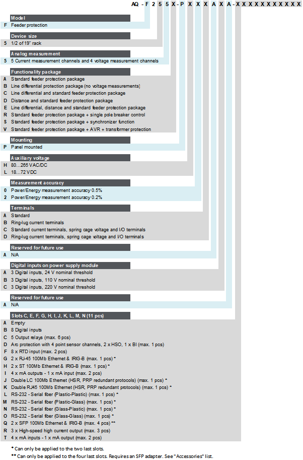
AQ-F255E offers a modular protection and control solution for line protection applications that require a large I/O capacity. It integrates line differential protection and distance protection as well as full feeder protection functionality in a single device.

Innovative line segment-based distance protection provides fast, selective and reliable protection by operating based on the principle of impedance measurement between the relay location and the fault point. The function allows protection schemes to be adjusted individually for each line segment using their real, independent impedance values instead of average values. This reduces the risk of unwanted operations through enhanced resistive reach and fault location accuracy, and improves selectivity and overall reliability. The segment-based distance protection can also distinguish between faults in underground cables and overhead line segments. Line segment-based distance protection also includes power swing block and out-of-step protection functions.

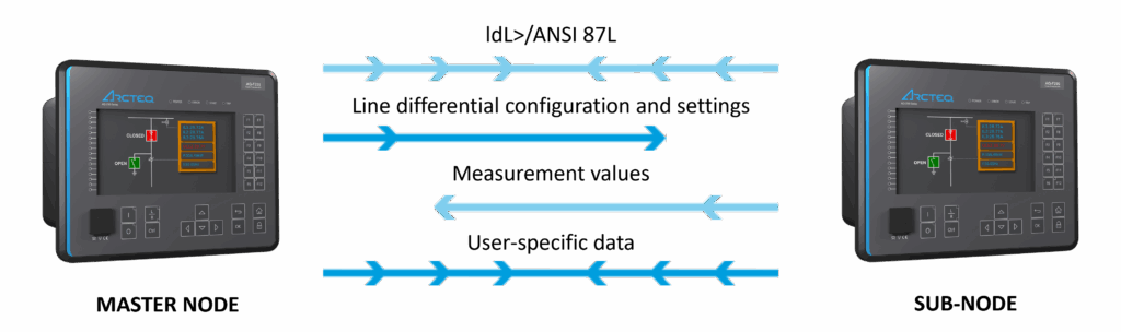
Line differential protection uses Arcteq’s smart dedicated process bus for communication between the master node and sub-node devices. It transfers both standard data and up to 64 user-defined signals, and automatically synchronizes the line differential protection settings from the master node device to the sub-node device. The process bus handles the compensation for delays in communication, which means that no external time synchronization is needed.

Line differential protection with a smart dedicated process bus.

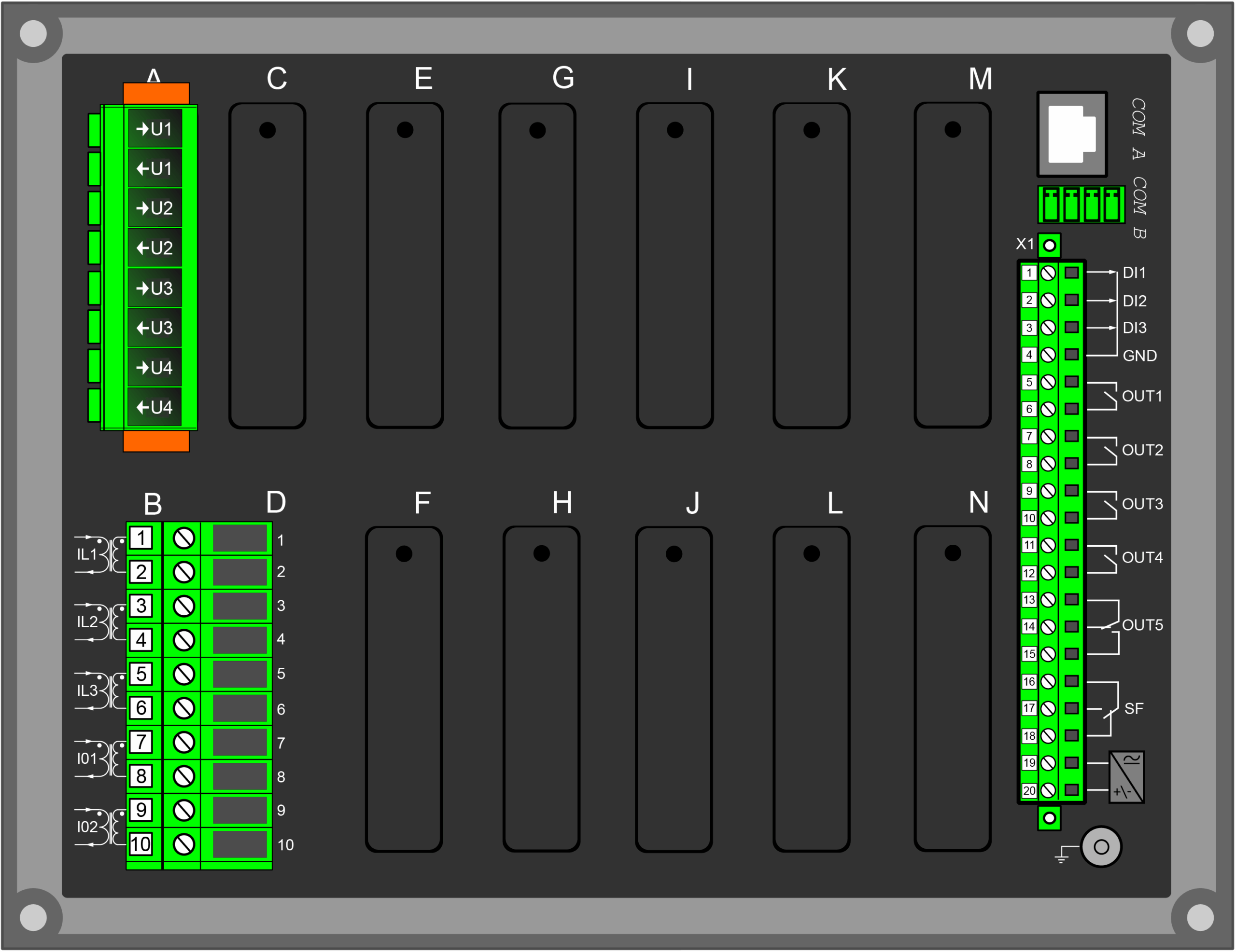
You can add up to eleven (11) I/O or communication modules into the device for extensive monitoring and control applications. AQ-F255E communicates using various communication protocols, including communication according to the IEC 61850 standard.

Highlights:

  • Innovative line segment-based distance protection function enhances resistive reach and fault location accuracy, particularly in mixed network, reducing the risk of unwanted operations.
  • Line differential protection for two line terminal ends:
    • Especially suitable for e.g. substations connecting wind and solar power facilities to the power grid.
    • Standard settings for communication – only the leader unit needs to be selected.
    • Master node device synchronizes transfers, configurations, and settings to the sub-node device.
    • Transformer in the protected zone.
  • Full feeder protection functionality.
  • 5-shot scheme-controlled auto-recloser.
  • IEC 62443-4-2 compliant cybersecurity (security level 1).
  • IEC 61850 2nd Edition.
  • A large I/O capacity.
  • Optional power and energy measurement accuracy of 0.2 %.

See all AQ-F255 line protection devices

AQ-F255_web

Technical data

  • Non-directional overcurrent (I>; 50/51) - 4 stages
  • Non-directional earth fault (I0>; 50N/51N) - 4 stages
  • Directional overcurrent (Idir>; 67) - 2 stages
  • Directional earth fault (I0dir>; 67N/32N) - 4 stages
  • Intermittent earth fault (I0int>; 67NT)
  • Negative sequence overcurrent/ Phase current reversal/ Current unbalance (I2>; 46/46R/46L) - 4 stages
  • Harmonic overcurrent (Ih>; 50H/51H/68H) - 4 stages
  • Circuit breaker failure protection (CBFP; 50BF/52BF)
  • High-impedance or low-impedance restricted earth fault/ Cable end differential (I0d>; 87N)
  • Overvoltage (U>; 59) - 4 stages
  • Undervoltage (U<; 27) - 4 stages
  • Neutral overvoltage (U0>; 59N) - 4 stages
  • Sequence voltage (U1/U2>/<; 47/27P/59PN) - 4 stages
  • Overfrequency and underfrequency (f>/<; 81O/81U) - 8 stages
  • Rate-of-change of frequency (df/dt>/<; 81R) - 8 stages
  • Low-voltage ride-through (LVRT; 27T)
  • Voltage-restrained overcurrent (Iv>; 51V)
  • Power protection (P, Q, S>/<; 32) - 4 stages
  • Line thermal overload (TF>; 49F)
  • Line differential protection (IdL>; 87L)
  • Distance protection (Z<; 21)
  • Power Swing Block (PSB; 68)
  • Out of step (OOS; 78)
  • Teleprotection (85)
  • Resistance temperature detectors (RTD)
  • Programmable stage (PSx>/<; 99)
  • Arc protection (IArc>/I0Arc>; 50Arc/50NArc) (optional)

  • Number of objects to control and monitor: 10
  • Number of indicators to monitor: 10
  • Number of setting groups: 8
  • Cold load pick-up (CLPU)
  • Switch-on-to-fault (SOTF)
  • Auto-recloser (0 → 1; 79)
  • Zero sequence recloser (U0> RECL; 79N)
  • Vector jump (Δφ; 78)
  • Synchrocheck (ΔV/Δa/Δf; 25)

  • Current transformer supervision
  • Voltage transformer supervision (VTS; 60)
  • Circuit breaker wear monitoring
  • Total harmonic distortion (current)
  • Total harmonic distortion (voltage)
  • Fault locator (21FL)
  • Measurement recorder
  • Measurement value recorder
  • Event recorder (max. 15,000 permanent event records)
  • Disturbance recorder (max. 100 records á 5 seconds at 3.2 kHz sampling)

  • Phase, sequence and residual currents (IL1, IL2, IL3, I01, I02)
  • Phase, sequence and residual voltages (UL1, UL2, UL3, UL12, UL23, UL31, U0)
  • Frequency (f)
  • Power and energy measurement accuracy of 0.5 %
  • Power and energy measurement accuracy of up to 0.2 % (optional)

  • Standard hardware
  • Current inputs: 5
  • Voltage inputs: 4
  • Digital inputs: 3
  • Digital outputs: 5
  • Number of empty slots: 11
  • Optional hardware modules
  • Digital input module (8 x DI)
  • Digital output module (5 x DO)
  • High-speed high-current output module (3 x out)
  • Milliampere input module (4 x mA in, 1 x mA out)
  • Milliampere output module (4 x mA out, 1 x mA in)
  • RTD input module (8 RTD inputs)
  • Arc protection module (4 x channels, 2 x HSO, 1 x BI)
  • Communication media (see "Communication" below)
  • External I/O modules (see "Accessories" below)

  • Communication inputs
  • RJ-45 100 Mbps Ethernet (front panel)
  • RJ-45 100 Mbps Ethernet and RS-485 (rear panel)
  • Optional communication modules
  • Double RJ-45 Ethernet & IRIG-B communication module
  • Double ST Ethernet & IRIG-B communication module
  • Double SFP Ethernet & IRIG-B communication module
  • Double LC (HSR/PRP) Ethernet communication module
  • Double RJ-45 (HSR/PRP) Ethernet communication module
  • RS-232 & serial fiber communication module
  • Communication protocols
  • IEC 61850 (edition 1)
  • IEC 61850 (edition 2)
  • IEC 60870-5-101/104
  • IEC 60870-5-103
  • Modbus/RTU and Modbus/TCP
  • DNP3
  • SPA

  • AX007 External 6-channel 2-/3-wire RTD input module (pre-configured)
  • AX008 External 8-channel thermocouple and mA input module (pre-configured)
  • AX013 Raising frame (120 mm)
  • AX014 Raising frame (40 mm)
  • AX015 Wall mounting bracket
  • AX020 SFP module (2 km, MM)
  • AX021 SFP module (40 km, SM)
  • AX022 SFP module (120 km, SM)

Additional material

Application Drawing

AQ-F255E application drawings v1.03

Device Rear Image

AQ-255 back panel

Device and Cut-out Image

AQ 250 dimensions and cut out 2025

Order Code

F255

Related products

Ask for an offer or more information

We provide a comprehensive range of services through our own skilled staff and a global network of partners.

Privacy Overview

This website uses cookies so that we can provide you with the best user experience possible. Cookie information is stored in your browser and performs functions such as recognising you when you return to our website and helping our team to understand which sections of the website you find most interesting and useful.

Strictly Necessary Cookies

Strictly Necessary Cookie should be enabled at all times so that we can save your preferences for cookie settings.

3rd Party Cookies

This website uses Google Analytics to collect anonymous information such as the number of visitors to the site, and the most popular pages.

Keeping this cookie enabled helps us to improve our website.